Phase Cancellation in Production Dialogue Recordings
Phase Misalignment Issues in Audio Post-Pro
When two microphones are used to record the same sound source, inevitably Phase differences arise. If the final image of the sound is mono, those differences will cause problems.
Here’s why.
Transmission of sound is a mechanical process, based on density variations of the medium in which it propagates. These variations are caused by the impact of the vibrations generated by the sound source. Typically, when air is the medium, an almost spherical series of alternating higher and lower pressure zones is generated, known as Sound Wave. When the Sound Wave pressure impacts a microphone’s membrane, this generates an electric current which, if then captured with a device that stores the whole series, is what we call a signal. That’s a recording.

The signal, then, is the electrical transduction of a mechanical Sound Wave, where higher pressure zone are marked as positive Phase and lower pressure zone are marked as negative Phase. Following the wave analogy, positive Phase’s shapes or crests are called peaks whilst the negative ones are called dips. A sound signal is always described as a series of alternating peaks and dips.
The Signal’s Phase Angle instead is actually a relative concept, given the fact it can only be measured with respect to a reference signal. A 180° Phase Angle is also called Reverse Phase or Phase Opposition. This means that – once the two signals are perfectly time aligned – then for each and every Phase Zone of the reference signal its opposite shape will occur in the analyzed signal.
Since the signal is given by electrical transmission, another concept needs to be cosidered separately from Phase Opposition: Polarity Inversion. This occurs when the microphone’s polarity is opposite to the polarity of the circuit devoted to signals transmission, amplification or recording. In this case, a Phase rotation of 180° can be adopted to achieve the correct transmission of the signal and thereby preserve the Phase’s Coherence throughout the cicuitry. That’s what that small ø button on Input Channels stands for.
Fig. 2 below is a screenshot of a widely diffused DAW’s timeline showing the waveforms of two signals, recorded with a standard pair of microphones: in blue is the Boom track, in yellow the Lavaliér track.
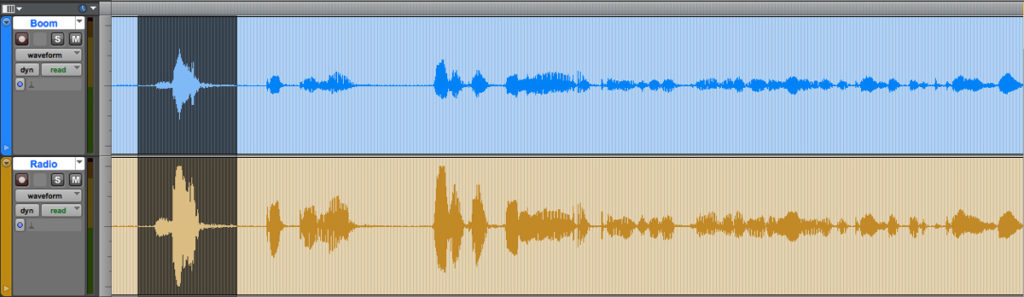
In the above image, at this level of zoom, no significant differences are perceivable: setting aside the small discrepancies in shape, the signals seem to be time-aligned and their similarity is testified by the alternating presence of the same transients at the same time. Despite those differences in signals simmetry and amplitude, the two waveforms seem to clearly show that the very same source was captured by both microphones.
But let’s take a closer look zooming in the selected area of both tracks.
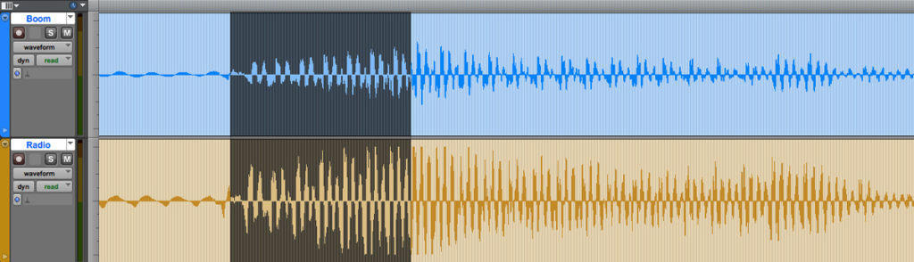
At this closer zoom level there are still no notable differences and also the Phase Coherence seems intact:
But zooming further down to samples’ level, something is clearly visible: the two signals aren’t Phase aligned and two things are noticeable:
1) the close similarity of shapes has almost vanished whilst the respective Phase Zone are still identifieable;
2) the alternate Positive and Negative Phase Zones appear to be sometime misaligned or even opposed.
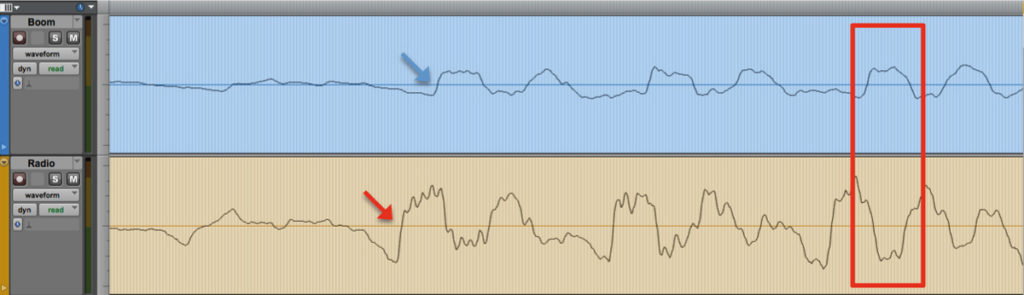
A more accurate analysis (beyond the borders of the above image) will show that the alignment difference is not due to any fixed offset but that it is a difference which changes in time according to the constantly shifting positions of the two microphones and their relative distance from the source. Thus no delay compensation or phase inversion can achieve anything more than apparent sporadic ‘improvements’ in the sum of the signals, simply adding a fixed offset either over time or in Phase.
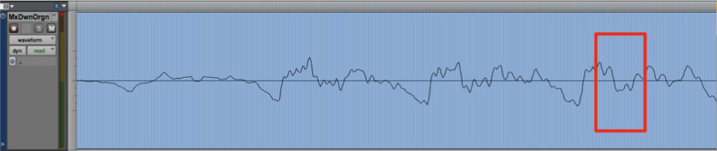
So, the simple sum of the two signals above will produce a very poor representation of the sound source, because of frequency cancellation. Figure 5 below shows the diminution of the signal’s amplitude corresponding to an almost perfect phase opposition point (shown in fig. 4 above) as well as of the overall modulation, even though the mixdown track has been vertically enlarged:
So, in order to restore a proper image of the sound source, the signals must first be perfectly aligned. This can be done manually but since the Phase difference changes constantly it’s a painstaking and very time-consuming task which the Sound Edtitor has to face.
When more than one single Lavaliéris present, things get even tougher.
This problem requires a technological solution which not only enables signals alignment but also guarantees the best achievable results in terms of acoustical clarity and quality. Figure 6 below shows in red the Boom track processed by the TimeLine Tools software which ensures perfect Phase alignment all along the track:
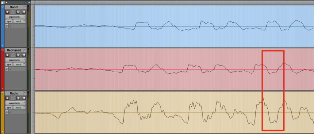
Figure 7 below shows the two mono Mixdown tracks. Up is the original Boom track plainly summed to the Radio track, below the aligned Boom track summed in place:
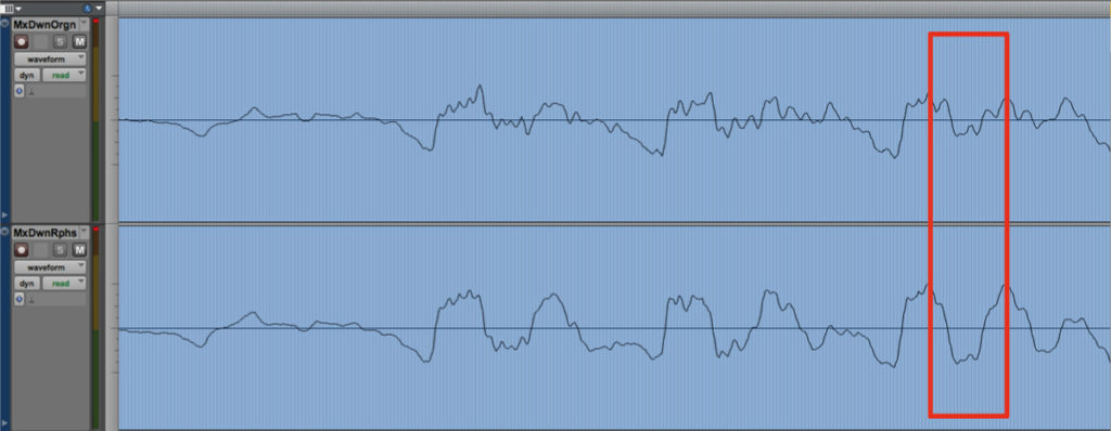
Constantly tracking the phase shift of the Boom signal against the proper Lavaliér track (the one which carries the actual speaker’s signal) the Software generates a copy of the Boom sound file which is always perfectly aligned with the various sources present in the multitrack take. This guarantees an optimum sound quality by preserving the original timbre and spatial image of all sound sources and avoids artifacts, Comb filter effects and frequencies cancellations.
Appendix – Phase Oddities: the Input Chain
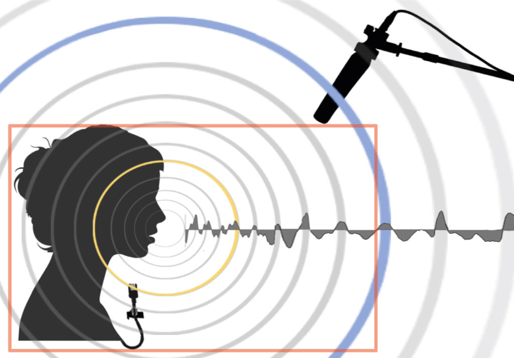
Fig. 1 shows the capture range of a typical Production Dialogue recording made on Set. In a 2D diagram the two microphones can appear as being in line, leaving aside their respective angles.
Similarly in Fig.2 we see an archer shooting at two consecutive targets (thin enough to shoot straight through). The arrow hits the bullseye (in yellow) of the near one and hits the further one slightly off-centre, in the blue area. Here the archer’s skill doesn’t matter at all, the point is: yellow first, blue second..
If the hits were signals then which signal would arrive first? The yellow one: the closer the earlier, common sense would respond.
In reality, sometimes the farther one comes first. Here’s why.
Radio microphones’ signals – as the name implies – are transmitted via Radio frequencies.

Unfortunately Radio frequencies, in the last 20 years, have become more and more crowded. Audio Recorders already have gone digital and so the natural solution has been to put the weight of the A-D conversion on to the transmitter’s shoulders. Despite legitimate considerations about quality, it does seem better to get a decent recording of a decent signal – digitally transmitted without interferences or signal drops – rather than record a beautifully sampled noise..
Nowadays A-D converters are cheap and small enough to fit in to a transmitter case, so quality isn’t such a problem. But speed still it is. In order to achieve speed, you need calculation power and calculation power needs… power. This means larger CPU, more supply, heat, circuitery and so on. Moreover, while the digital (radio) transmission needs a very small bandwith compared to the analogue one, that bandwith has to be filled with a large amount of long sequences of “0” and “1” thus a larger buffer. All this produces latency on the Radio microphones Input chain.
We would be right in thinking therefore that the ADC of a digital Field Recorder has lower latency than that of the transmitter. Latency as an absolute value – below certain thresholds – doesn’t produce any significant damage to the recorded material as a whole. Please remember that the recording has always to be considered as a whole and the sound of a given take will result always from a mix – more or less carefully made – involving the sum of all signals. The problem arises with relative latency which means the delay between the microphones on stage.
Consider this very common scenario:
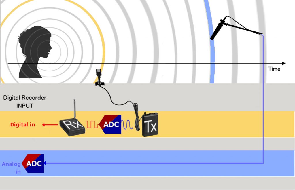
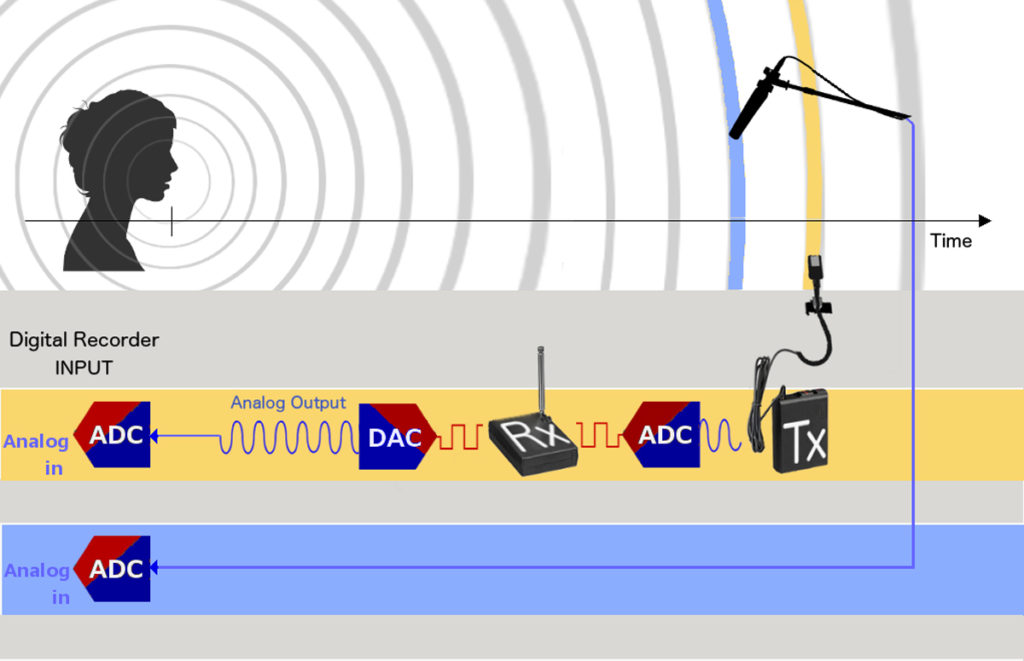
– one Radio Microphone plugged in a (digital) transmitter which then goes to the recorder’s Digital Input;
– the Boom plugged straight in the Analog Input of the (digital) recorder by cable.
The cabling shown in Fig. 3 doesn’t affect the quality of the recording and has a small impact on the signals phase, but for the fact that the Boom could arrive few samples before than expected, but the Lavaliér nevertheless will win the race.
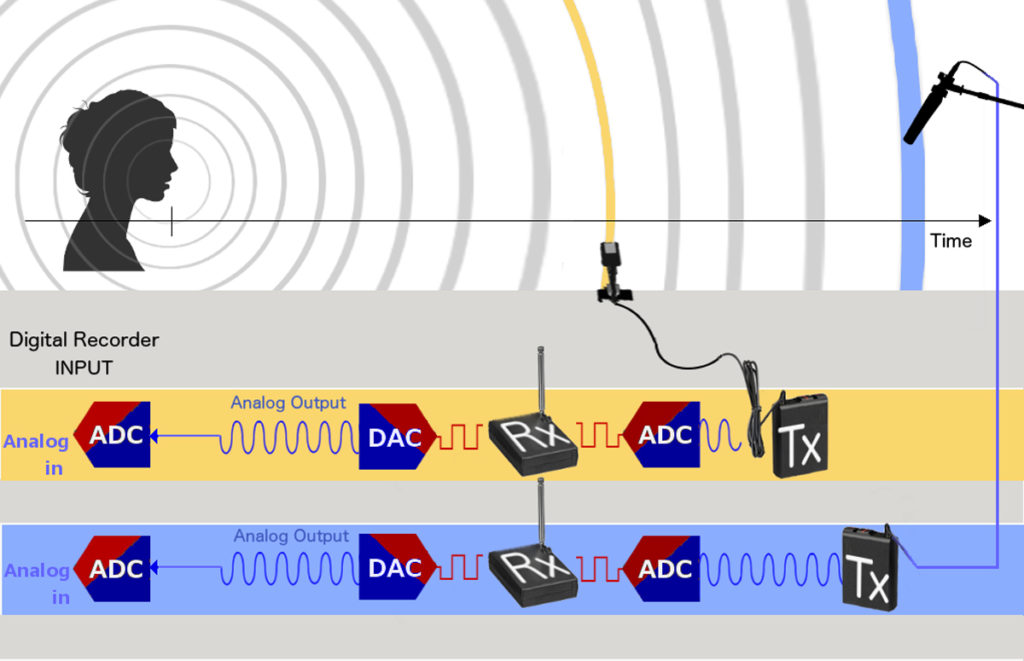
In order to fix this not so invasive latency discrepancy, the simplest solution is to always keep both microphones on the very same transmitter-ADC chain as shown in Fig. 4.
You may notice that in Fig. 3 above, the blu wavefront and the Boom icon are closer to the source, at the same ideal distance as shown in Fig. 2 whereas here in Fig. 4 the latency produced by the digital transmission has been added to the Boom icon and relative wavefront.
The Lavaliér microphone is always shown with its own latency added to its ideal position in Time (see Fig. 2).
The reference line is marked as Time but the terms Time and Space can be easily swapped here: Time is nothing else than the signal’s image of microphones distance.
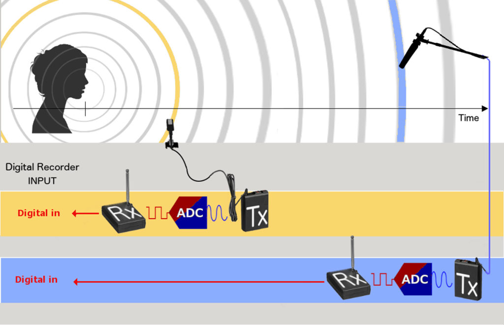
The cabling scheme, shown in Fig. 5, simply adds a large amount of total latency, given the fact that 3 consecutive A-D and D-A conversions are made along the Input chain. Despite the fact that this cabling scheme makes no sense at all, it is surprisingly often used to overcome missing bits of equipment, even trivial connectors, or else simply because of a lack of awareness about latency buildup.
Finally, this is a clear example of a paradox or oddity that makes the Boom actually win the race.
This case – in which the Boom comes first – is not so rare as to be ignored, just the opposite: it happens so frequently that it is definitely worth considering.
Given the fixed ratio Space/Time due to Sound Propagation Velocity (344 m/s assumed uniform and stable in air at 21°C) we can explain both Time and Space measurements, in the Digital Domain, in terms of samples.
So let’s make some calculations: at 48kHz of sampling rate, 1 ms of latency means that the signal arrives 48 samples later.
If a chain such as that in Fig. 6 is adopted, then we’ll get three times that delay, plus the buffer-induced latency, easily ending up more than 120 samples later.
Now, the average distance between the two microphones is around 1 m or less when the camera field is relatively narrow. In this example let’s assume 71,666 cm which corresponds to exactly 100 samples. 71,666 cm is also the Wavelength of a 480 Hz Frequency.
The Cancellation obviously occurs at 180° of Phase rotation which happens when the frequency’s wavelenght corresponds to twice the distance between the microphones, so with a distance of about 72 cm, the frequencies around 240Hz would be affected the most by cancellation. Bear in mind that in this example both distance and frequency are realistic for an actual recording and 240 Hz is quite a crucial component in the mid-low range of the human voice.
Since Phase is dependent on frequencies, and the human voice is quite a complex signal with various harmonic components, the actual end result of the Phase misalignment is almost unpredictable but what is for certain is this: the resulting delay in the Input chain which almost corresponds to the distance between the two microphones adds a substantial undesired side effect on to the already acknowledged Phase problem: the cancellation bounces back and forth between the frequencies. By moving the Boom away the signals from the Radio microphone will be recorded slightly earlier whilst in a narrower shooting this will happen to the Boom instead. This alternating behaviour renders manual Phase Alignment an absolute nightmare for the Dialogue Editor.
Even the opposite can happen: sometimes the Sound Crew does a terrific job on set but its commitment is sorely compromised by lack of knowledge of the Phase Alignment problem in the Sound Editing Department.
So, to sum up, do try to avoid recording on different Input chains the Boom and the various Radio microphones which together constitute the overall sound image. Do use Digital Inputs when using digital transmitters, a plug-on to transmit the Boom as well and, should there be a shortage of Input sockets, try packing the signals with a good quality passive digital router.